Product Programming and Test bench
This a completely customizable tesing and programming bench for printed circuit boards that can be used in small scale production.
Vision
We all know how important it is for any hardware company to ensure that each product that they ship provides the same efficiency which was is promised to the customer. For this the product has to undergo a series of quality control testes before the final firmware is loaded and the product is packaged for shipping. This is often manual in small firms producing various products. During my summer internship I was presented with the problem and was asked to come up with a solution that can reduce the manual process of testing each component and hence increasing speed and reducing human error while keeping the price low. A rig was built that enabled the company to program as well as test the circuits produced automatically, hence, improving the quality and productivity during manufacture of the product.
Useage / Working
The complete setup can be broken into 3 main parts viz.
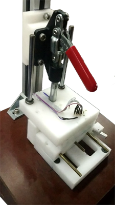
- The mechanical contraption
- The embedded hardware and
- The operating software
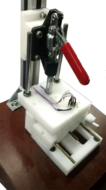

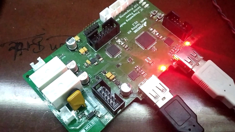
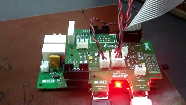
This rig connects to a computer via USB to communicate the progress. To test/program a device the technician lifts the lever to reveal the machined slot where the circuit fits perfectly. The circuit is placed in that groove and the lever is pulled back down, making secure connections to the test-pads as well as to the programming pads.
The device then undergoes a series of tests designed for the circuit before it is finally programmed and packaged.
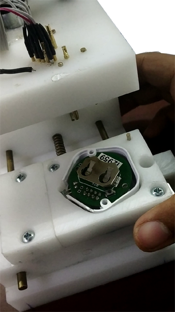
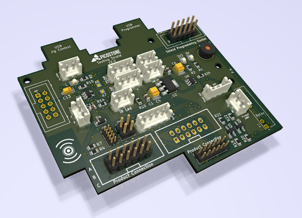
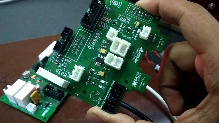
The mechanical design was easily adaptable to any new product simply by replacing the “product cassette” or the pin/pad configurations and the product slot. There were a bunch of sensors included in this cassette to test functionality of components such as IR Led, RF antenna transmit and receive range etc.
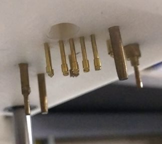
The upper plate consisted of pogo pins, which are simply spring-loaded contact pins along with some placers which are used to align the circuit board relative to these pins.
The product or the test circuit for this type of testing requires to have exposed pads for the pins to connect to as opposed to In Circuit Testing.
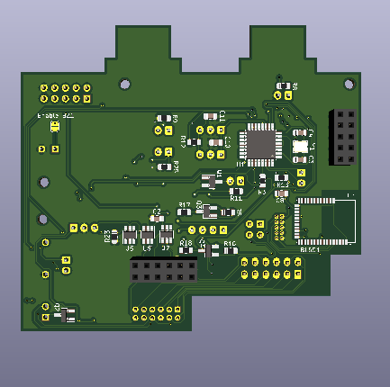
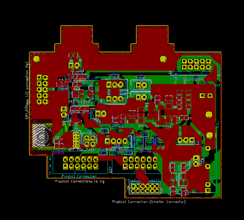
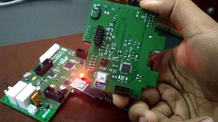
The main components of the design were ATMega 328 and a NRF52. The Wi-Fi functionality was also tested using the ESP32 connected to the base board.
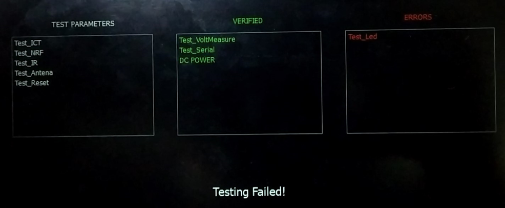
The design included various independent circuits to test for different parameters simultaneously. This board was capable of performing tests related to:
- Power Management
- Antenna Power and SNR
- BLE and Wi-Fi Connection
- LED
- UART and SPI Bus
- Tactile switches or buttons
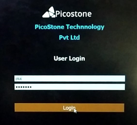
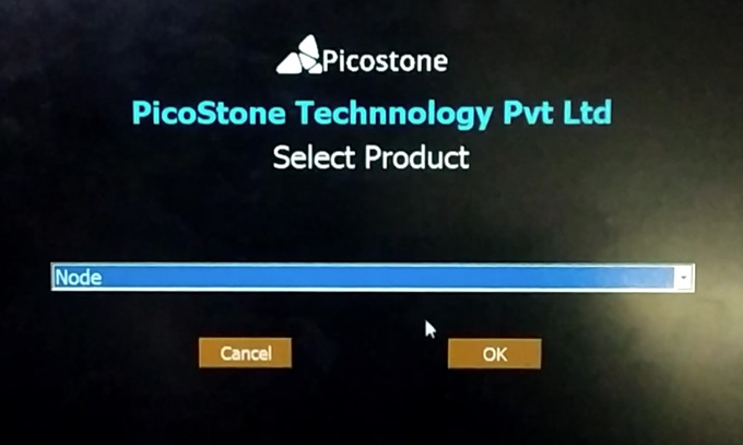
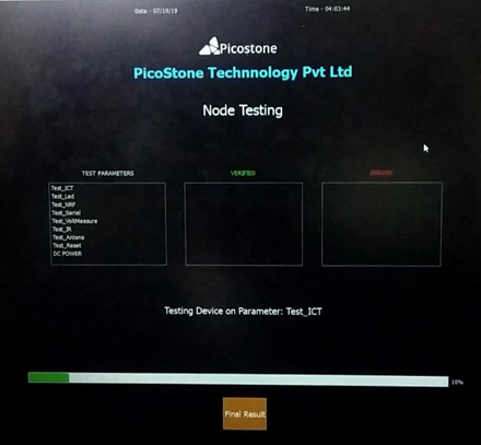
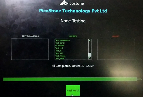
This PCB communicated to the host PC Running a python-based application to display progress as well as to select various operations or testes required by the particular product.